⏱️ 555 Timer: The Workhorse IC
The 555 timer is one of the most popular ICs ever made.
Introduced in 1972, it's still manufactured by the billions every year.
Why? Because it's:
- Versatile (timing, oscillation, pulse generation)
- Simple (minimal external components)
- Reliable (works from 5V to 15V)
- Cheap (cents per chip)
- Robust (hard to kill)
🎯 What Can the 555 Do?
The 555 timer can operate in three modes:
| Mode | Function | Output |
|---|---|---|
| Monostable | One-shot pulse generator | Single pulse when triggered |
| Astable | Free-running oscillator | Continuous square wave |
| Bistable | Flip-flop | Toggle between states |
We'll focus on monostable and astable (most common).
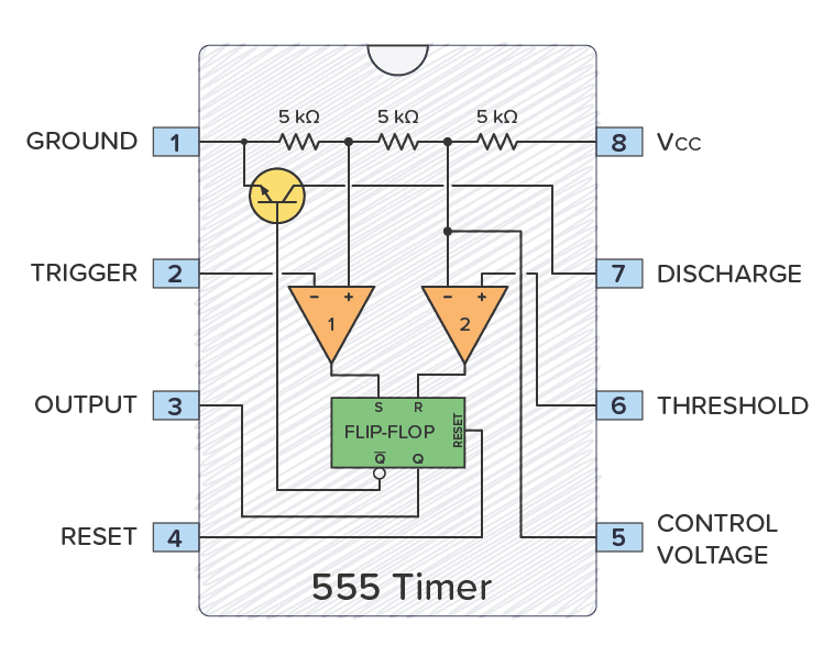
🏗️ Inside the 555 Timer
The Block Diagram
The Pins (8-pin DIP)
| Pin | Name | Function |
|---|---|---|
| 1 | GND | Ground |
| 2 | TRIG | Trigger input (starts timing) |
| 3 | OUT | Output (high or low) |
| 4 | RESET | Reset (active low) |
| 5 | CTRL | Control voltage (usually bypassed) |
| 6 | THRES | Threshold (stops timing) |
| 7 | DISCH | Discharge (internal transistor to ground) |
| 8 | Vcc | Power supply (+5V to +15V) |
🔍 How It Works Internally
The Voltage Divider
Three 5kΩ resistors divide Vcc:
- Upper comparator reference:
- Lower comparator reference:
Comparator Action
Upper comparator:
- Monitors THRESHOLD (pin 6)
- When THRESHOLD > → resets flip-flop → output goes LOW
Lower comparator:
- Monitors TRIGGER (pin 2)
- When TRIGGER < → sets flip-flop → output goes HIGH
Discharge Transistor
- Connected to pin 7
- ON when output is LOW → grounds external timing capacitor
- OFF when output is HIGH → allows capacitor to charge
Remember these voltages for a 555 on 5V supply:
- Trigger threshold:
- Upper threshold:
These determine when the timer starts and stops!
🎯 Monostable Mode: The One-Shot
What It Does
When triggered, output goes HIGH for a precise time period, then returns to LOW.
Perfect for:
- Debouncing buttons
- Generating precise delays
- Pulse stretching
- Timeout circuits
The Circuit
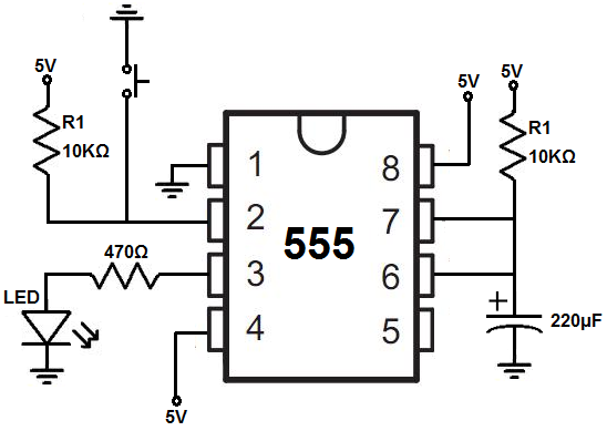
- Vcc to pin 8 and pin 4 (RESET tied high)
- Pin 2 (TRIG) through pull-up resistor to Vcc
- Trigger button from pin 2 to ground
- Pin 5 (CTRL) bypassed with 0.01µF to ground
- Timing components: R between Vcc and pin 7/6
- Timing capacitor C between pin 6/7 and ground
- Pin 3 (OUT) to load (LED + resistor)
- Pin 1 to ground
The Timing Formula
Where:
- = output pulse width (seconds)
- = timing resistor (ohms)
- = timing capacitor (farads)
📐 Design Example: 10-Second Timer
Goal: LED turns on for 10 seconds when button pressed
Design:
Choose (common value)
Calculate :
Use standard value:
Result:
- Press button → LED on for ~10 seconds
- Automatically turns off
- Can be re-triggered immediately
⏱️ Timing Component Selection
| Timing Range | Resistor | Capacitor |
|---|---|---|
| Microseconds (1-100µs) | 1kΩ - 100kΩ | 10pF - 1nF |
| Milliseconds (1-100ms) | 10kΩ - 100kΩ | 10nF - 1µF |
| Seconds (1-100s) | 100kΩ - 10MΩ | 1µF - 1000µF |
| Minutes (1-10min) | 1MΩ - 10MΩ | 10µF - 100µF |
- Minimum R: 1kΩ (chip can source ~200mA max)
- Maximum R: 10MΩ (leakage currents cause errors)
- Minimum C: 100pF (stray capacitance matters)
- Maximum C: 1000µF+ (watch leakage)
For very long times, consider using a microcontroller instead!
🔄 How Monostable Works (Step by Step)
Initial State: Output LOW, capacitor discharged
1. Trigger Applied (pin 2 pulled below 1/3 Vcc):
- Lower comparator triggers
- Flip-flop sets
- Output goes HIGH
- Discharge transistor turns OFF
2. Capacitor Charges (through R):
- Voltage rises exponentially toward Vcc
- Output stays HIGH
3. Threshold Reached (pin 6 exceeds 2/3 Vcc):
- Upper comparator triggers
- Flip-flop resets
- Output goes LOW
- Discharge transistor turns ON
- Capacitor rapidly discharges
4. Ready for Next Trigger
🚀 Monostable Applications
1. Button Debouncer
Mechanical switches bounce: one press = multiple pulses.
Solution: 555 monostable with T = 10-50ms
- First bounce triggers timer
- Output stays HIGH (ignoring subsequent bounces)
- Clean single pulse to microcontroller
2. Missing Pulse Detector
Monitor periodic signals (heartbeat, sensor pulses).
Setup: Trigger from signal, T = 1.5× expected period
- Normal pulses keep retriggering → output stays HIGH
- Missing pulse → timeout → output goes LOW (alarm!)
3. Precise Delay
Need a delay that's independent of software?
Use 555: Button press → delay → activate relay
- Purely hardware
- No microcontroller needed
- Very reliable
4. Touch Switch
Capacitive touch sensor triggers 555 monostable.
- Touch detected → LED/device on for set time
- Auto-off after timeout
💡 Design Tips for Monostable
-
Prevent False Triggering:
- Pull pin 2 HIGH with 10kΩ resistor
- Add 0.01µF capacitor from pin 5 to ground
-
Reset Pin:
- Tie pin 4 to Vcc (through 10kΩ) for normal operation
- Ground pin 4 to force output LOW (external reset)
-
Bypass Control Voltage:
- Always add 0.01µF cap from pin 5 to ground
- Prevents noise-induced false triggers
-
Timing Accuracy:
- Use 1% tolerance resistors
- Use quality capacitors (film or ceramic C0G)
- Actual time = 1.1RC ± 1%
-
Retriggering:
- 555 can be retriggered during timing
- New trigger extends the timing period
- Useful for watchdog timers
🔧 Troubleshooting Monostable Circuits
| Problem | Likely Cause | Solution |
|---|---|---|
| Output always HIGH | Trigger pin floating low | Add pull-up resistor to pin 2 |
| Output always LOW | Reset pin floating low | Tie pin 4 to Vcc |
| Random triggering | Noise on trigger/control | Add bypass caps, check wiring |
| Wrong timing | Wrong R or C values | Recalculate, measure components |
| Won't trigger | Trigger not going low enough | Check trigger level (<1/3 Vcc) |
| Won't reset | Capacitor not charging/discharging | Check connections to pins 6/7 |
🧪 Lab Exercise 1: Build a Reaction Timer
Objective: Measure reaction time
Circuit:
- Button triggers monostable
- LED lights for exact 1 second
- User must press stop button before LED goes off
- If successful, second LED lights
Components:
- NE555 timer
- Resistors: 10kΩ (pull-up), 91kΩ (timing), 330Ω (LED)
- Capacitors: 10µF (timing), 0.01µF (bypass)
- LEDs, buttons
- Optional: Add second 555 for scoring
Learning Goals:
- Monostable operation
- Timing component calculation
- Button interfacing
- Cascading logic
🎲 Fun Project: Electronic Dice
Circuit:
- 555 astable oscillator (very fast, we'll learn this next!)
- Feeds binary counter (we'll learn digital circuits later)
- Press button → counter stops at random number
- Display on 7-segment display
Your contribution: The 555 timing circuit!
✅ Monostable Summary
Key Points:
- One-shot pulse when triggered
- Output HIGH time =
- Trigger: Pull pin 2 below 1/3 Vcc
- Threshold: When pin 6 exceeds 2/3 Vcc, output goes LOW
- Can be retriggered during timing
- Pin 4 (RESET) forces output LOW when grounded
Common Uses:
- Delays and timeouts
- Debouncing
- Pulse stretching
- Missing pulse detection
- Touch switches
🎓 Looking Ahead
In the next lesson, we'll explore Astable Mode where the 555 generates continuous oscillations!
We'll build:
- Flashing LEDs
- Square wave generators
- PWM controllers
- Alarm circuits
- And more!
📚 Further Reading
- Build a monostable circuit and measure timing accuracy
- Experiment with different R and C values
- Try retriggering during the timing period
- Measure voltages at pins 2, 6, and 7 with oscilloscope
- Design a practical debouncer for your next microcontroller project